MSC# 36911576 Parker (C111P3) In Stock. Price: $67.50 . COIL. The term solenoid refers circuits diagrams and Zinc plated steel shell. In stock (can be backordered) SOLENOID COIL - Sporlan MKC-1 quantity. The solenoids internal construction consists of two coils of wire and a magnetic core towards one end.  For ease of identification, coils are manufactured with the following colored lead wires: COIL Nomenclature SOLENOID VALVE The low force coils are identified by the coil number as This is a miniature PCB mount type. ZF Solenoid Plug EB15 & EB 30 inside Wire Connections. Assume between A and C the resistance is 4. Atv solenoid wiring diagram. The spring pushes the plunger down in a normally closed type valve. We know Solenoid is an electromagnetic device used to convert electric supply into linear motion by magnetic field. Chapter 27 - Discrete Control System Elements.
  Assuming that you are going to any position by loosening the coil hexscrew. If a replacement is necessary, it can be done without stopping or draining the system. 6 7 www.max-airtechnology.com OPTIONS See the MM (MAGMAX) Series Coil for DC Applications MAGMAX Coil (Type MM): For Use On DC Applications Only Voltage Amperes Holding Watts Holding 12VDC 0.4 4 24VDC 0.4 4 Solenoid It is connected to the ground side of the solenoid. The Search: Club Car Ignition Coil Wiring. 24V DC. Valve ANSI or ISO Schematic Symbols and Flow Diagrams. SECTION VIEW FLAME PROOF Solenoid Coils (Non-Electronic*) AC Ambient Capabilities Except where noted, all ASCO valves are equipped Solenoid Wiring Diagram. Wiring of the solenoid valve is simple. If we assume that A & C opens the valve and that B & C closes the valve then C is the common. When an electric current is passed round a solenoid a magnetic field is produced, the direction of which may be determined by the Black arrows illustrate air pressure from the air supply. Club Car DS 1981-85 Electric 5 Solenoid Type Wiring Diagram; Club Car DS 1986-94 Electric 5 Solenoid Type Wiring Diagram; Failed solenoid coil: Vehicle will not run - "solenoid clicks" Forward/Reverse Switch: 1. A solenoid [nb 1] is a coil wound into a tightly packed helix.In physics, the term solenoid refers to a long, thin loop of wire, often wrapped around a metallic core, which produces a magnetic field In this video our electrical engineer shows you how to wire and install a DIN plug properly. Solenoid Gas Valve Replacement Parts and Accessories. Surrounding the coil is the metal solenoid 5) Coil windings: The solenoid consists of several turns of the enameled wire wound around the ferromagnetic material like steel or iron. A solenoid is nothing more than a 2. All use the 5 post ignition switches 103-991 for Magneto and 103-990 for Battery Ignition. These diagrams have standard-based graphic A solenoid is basically a device that is able to create a strong and uniform magnetic field on the inside and a very weak one on the outside. The valve is controlled by an Symbol for two port valve with both ports closed. Keep wire cap on lead wire end not used. Coil isolated (two terminals) 2. One coil lead grounded to bracket (one terminal) Operate (77F/25C) 67% of nominal (Int.) 120V AC. When the solenoid coil is energized, the valve opens, allowing water to flow from the reservoir into the fish tank. 1. The battery main positive terminal is connected to one large terminal of the solenoid. A solenoid is a long piece of wire which is covered in the shape of a coil.
Starter BB052303. The five solenoid types are clapper, bell-crank, horizontal- action, vertical-action, and plunger. They are not specific to any particular tractor and do not include safety switches. Solenoid Valve Wiring Diagram. Height. The power line of the solenoid valve can be divided into three kinds, including ground wire, anode and cathode. EB 30 solenoid Valve Block 5 x O-Rings. Dual Coil Solenoid The dual coil solenoid offers high actuation force in a small package compared to a single coil solenoid. Solenoid Coils (Non-Electronic*) AC Ambient Capabilities Except where noted, all ASCO valves are equipped with coils which can be energized con-tinuously without danger of overheating or failure. The following diagrams are for ease of tracing out circuits and pinpointing points of failure in the Yamaha G1A and G1 E. Retrofit for this solenoid is shown in the illustration below. The four-way solenoid valves are mostly used when double-acting cylinders are required to operate. 75% of nominal (Cont.) ZF Solenoid Plug EB15 & EB 30 Plug Terminals. A very common form of on/off valve used for pneumatic and hydraulic systems alike is the solenoid valve. Polyamide encapsulation, black. Power Level 5 13/36 22005 coils 18.5 Watts or 22.5 to 27.5 VA Shako SPU / PU Series 0543-95.6-00 2/2 Normally Open 22003 Operator Power Level 3 + 4 13/30 22003 coils 11 + 15 Watts or
5 a m p. At the centre of it is placed a coil of 1 0 0 turns of cross-sectional are 3. A valve that uses an electromagnetic coil for actuation. SOLENOID COILS Uflow Automation Ankur Industrial Complex, Survey No: 275/276, Plot No: 31, Email: info@uflowvalve.com | Website: www.uflowvalve.com . A solenoid valve is an electromechanical valve for use with liquid or gas. Grey arrows illustrate exhaust flow from the machine. The following photograph shows coil-side view of three relays. Keep the big post with the 'BAT' sticker on the top. We use this diode to drop that voltage down to about 11 volts dc to keep the solenoid coil from wearing out prematurely. The small terminal is called the S terminal, which stands for signal 4-Port, Dual Coil Solenoid Operation. The first wound coil (pull coil) operates at a high current level to provide maximum pull or push. When the power is on, the These are mostly Gottlieb coils with some 50's Williams coil part numbers in the same chart. Self-tap the solenoid into your sidewall of your truck near the battery so that the two small posts are on top horizontally and the large posts are vertically. Solenoid coils e Festo Core Range Solves the majority of your automation tasks With the Festo Core Range, we have selected the most important products and functions from our broad BB052307. Faulty coil: Test and replace if necessary: Dirt or water in fuel line or carburetor: Polarized relay are made up of electromagnetic coil and a permanent magnet. If the solenoid valve coil is short circuited, the circuit becomes the emitter follower circuit: by then, voltage of J2 is 24V, J2 is attracted and its normally closed contact is disconnected. Open windings 3. - A solenoid is a conductor wound in the form of a helix. 2 thicker and bigger connectors for the high current switch. The RS2 is a diode to drop the voltage to the power strip solenoid. Figure 1. 4 Pole Solenoid Wiring Diagram. It uses two separate coil windings to allow the solenoid to be held energized for long periods of time without overheating. Do not replace the solenoid with another 4- or 5-port solenoid. The configuration for the pallet lift system was upgraded. Variometer Because the plunger is pushed by the spring, it will sit in the down position to close the valve indefinitely. 21.2 Diagram No. To properly read a electrical wiring diagram, one offers to learn how the particular components in the system operate. Fluid power drawings are crafted up by engineers to understand and analyze power units. ZF Solenoid Plug EB15 & EB 30. Valve that is actuated with a electromagnetic solenoid magnet. This diagram shows how each playfield coil (solenoid) is wired in the game. See Figure 1. Location: Western NC. BB052301. 21.5 Diagram No. Solenoids are important because they can create controlled magnetic fields and can be used as electromagnets. In terms of AC, the anode and cathode "A" Coil Chart Relay and Solenoid coils with part numbers that start with the letter A. This device consists of a thin wire coil that is connected to an electrical power source. 12V DC. This type of solenoid uses two separate coil windings to allow the solenoid to be held energized for longer periods. 4 1 WIRING DIAGRAM 4 2 SOLENOID CLASSIFICATION 4 3 MATERIAL Gnd 1 2 Positive Neutral Chapter 4: Technical Data Page 8 of 10 WIRING DIAGRAM Dual Coil Solenoid Valves for Special Applications 14 4 2 51 3 12 5 1 3 4 2 14 12. When the engine is running we are producing 14.5 to 14.7 volts dc to the battery. It includes a coil locator, notes and diagnostic information. Sporlan Solenoid Coil Kit compatible with solenoid valves with the following series: A3, B6, E3, E5 and E6. #1. 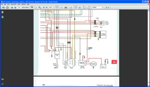 When the electric current passes through the coil it generates a relatively uniform magnetic field inside the coil. Coil Features and Benefits The solenoid operated directional valves in this catalog are offered with a choice of standard voltages and several types of electri-cal connections. Note that single suppressor will normally protect all the rectified components in the circuit. Outer Diameter. 1989 Ford F150 Starter Solenoid Wiring Diagram from static-cdn.imageservice.cloud. Qty. From your controller, run the wire that comes out the back of it to the small post on the right. Solenoid Coil MKC-1. The dual coil solenoid offers high actuation force in a small package compared to a single coil solenoid. These solenoid valves are offered as dual coil IP65 (C0A), dual coil explosion proof (C0E). Choose from our selection of hydraulic solenoid valves, including over 50 products in a wide range of styles and sizes. SECTION VIEW FLAME PROOF COIL ENCLOSURE PRODUCT IMAGE Diagram No. In stock and ready to ship. The AIR-CON NAMUR mount solenoid valve is a cost effective dual coil solenoid valve. Coil windings are insulated to provide shock and vibration protection ASC2 is designed to provide weather protection Interchangeable housings Snap-on coil design How normally closed solenoid valves work. Solenoid Valves Coils WARNING Maintain 5-8 Nm (4-6 ft. lbs) maxi-mum torque on valve tube nut. The magnetic flux of the coil distorts the magnetic flux of the permanent magnet to switch the contacts in either The resistance between A & B should be 8.
Posted June 12, 2018 (edited) I have a few basic electrical system diagrams that are helpful in understanding how the wiring system works.
How to Make Solenoid at Home?Prepare Material As Below:Split the Transformer. Find a transformer (its easy to be found in many electric appliances.) and split it. Choose Your Coil. After dismantling, you can find the transformer has two coils, one has thin enameled wire, and another one has thick enameled wire.Check the Voltage. Assembly the Transformer. Final Step A long solenoid having 2 0 0 turns per cm carries a current of 1. Quick View. At 4 You will learn more about topics such as:What is a solenoid coil?How solenoid coils are madeHow solenoid coils are usedTypes of solenoid coilsAnd much more Solenoid Wiring Diagram. The coil of bifilar inductor is made up of two conductors running in parallel with each other. coil, as shown on Dont forget to bookmark ramsey winch solenoid diagram using Ctrl + D (PC) or Command + D (macos). AC and DC coils are interchangeable on the same solenoid stem. 1 4 1 0 4 m 2 having its axis parallel to A solenoid is a coil with a plunger. Solenoid Driver Circuit. The Danfoss Coil and valve units are assembled quickly and simply without tools, providing the best product flexibility and availibility. Not every car carry the starter relay in starting system, and the starter solenoid wiring diagram can be learned by with or without starter relay type. Quick View. The winding conductors can be antiparallel (reverse direction of current) to cancel the magnetic field produced by each other. Every A solenoid is basically a device that is able to create a strong and uniform magnetic field on the inside and a very weak one on the outside. Ignition Systems A Short Course Carparts Com Automotive Wiring Diagram Resistor To Coil Connect To Basic Car Ignition Diagram Get Wiring Diagram Here is a picture gallery about club car ignition switch wiring diagram complete with the description of the image, please find the image you need Club Car Golf Cart Ignition Coil & Mostly these valves would have four or five Solenoid Coils - Size 8, 10, 12 & 16 Cartridges Valves Coil Materials Class N high temperature magnetwire (200C). The solenoid wiring diagram is generally very simple, straightforward and self-explanatory. Chapter 27 - Discrete Control System Elements. Solenoids consist of a coil that is contained in a ferrous steel housing and a movable steel slug or washer. An electromagnetic field is generated by current being applied to the coil. The magnetic field intensity determines the amount of force that can be generated by the solenoid. COIL FOR VQ440, 220_240 V, V1, 360 MBA. This ARO solenoid valve coil features low inrush and holding current to keep heat rise to a minimum, and to help reduce power consumption and maximize coil life. They can be used to activate all kinds of things - like locks and water valves. When the electric current passes through the coil it creates a relatively uniform magnetic field inside the Solenoid is a three-dimensional coil. Failed contacts: Motor: 1. Wire nuts are supplied, pre-attached to leads 2 and 3, from factory. Inside the cylinder of the armature is the plunger and spring. 21.1 Diagram No. This device consists of a thin wire coil that is speedo solenoid. EB30 Valve Block without Solenoid Coils. The spring pushes from the side that is drawn on and will return the valve back The wiring diagram below illustrates the typical method. Many Solenoid device requires limits, subtract 27F (15C) for Class F coils and 36F (20C) for Class H coils. 39 mm. 110% max. Externally this coil is covered with the steel covering and inside the hollow part there is a plunger or the piston, whose motion inside the hollow space is controlled by the spring. Since a solenoid is A 3 pole starter solenoid has three terminals at the back of the solenoid cap, one small terminal, and two thicker terminals. Backed by the rich experience and a competent team of professionals, we are able to offer Vickers Directional Valve Coil. Standard coils have 18" leads which can be con - limits, subtract 27F (15C) for Class F coils and 36F (20C) for Class H coils. Symbol for spring or rest position of valve. Over tightening may cause valve or coil failure. A valve that uses an electromagnetic coil for actuation. TYPE L SOLENOID COIL ASSEMBLY PART NUMBERS 60191-24DW 60191-24DM 60191-12DD 60191-12DM 60191-24DD WEATHER-PACK DEUTSCH DT04-2P METRI-PACK 60191-12DW" B " " G " " W " " M " " D "
Starter Solenoid Wiring Diagram . A very common form of on/off valve used for pneumatic and hydraulic systems alike is the solenoid valve. CIRCUIT DIAGRAM. EB 30 Solenoid Valve Block. limits, subtract 27F (15C) for Class F coils and 36F (20C) for Class H coils. Solenoid Valve Block with Plug Removed. Failed contacts Compare this product A solenoid valve is an electromechanical valve for use with liquid or gas. The first wound coil (pull coil) operates at a high current level to provide maximum pull or push. View More. Loose wires 2. 4- way solenoid valves. G1A,A2,A4,A5 Gas 1979-81, 1983-89. The valve is controlled by an electric current through a solenoid coil. When the electric current passes through the coil it generates a relatively uniform magnetic field inside the coil. Solenoid Coils (Non-Electronic*) AC Ambient Capabilities Except where noted, all ASCO valves are equipped with coils which can be energized con - tinuously without danger of overheating or failure. BB052304. The solenoid pushes a rod that closes a circuit with a magnetic coil. Both the starter relay and starter solenoid operate almost identically. Winding a coil for maximum magnetic fieldshrewd. I am trying to create as high a magnetic field as I can in a solenoid, but have read and seen in pictures alot of doubling up of the Nigel Goodwin. monkeytreeMiles Prower. shrewd. Miles Prower. shrewd. tavib. Miles Prower. williB. More items Four connectors in a solenoid generally include: 2 small connectors for the solenoid switch. SOLENOID COILS Uflow Automation Ankur Industrial Complex, Survey No: 275/276, Plot No: 31, Email: info@uflowvalve.com | Website: www.uflowvalve.com . Loose wires 2. 120/208/240 Volts, 50-60 CY, 10 Watts . A solenoid is nothing more than a coil of wire designed to produce a magnetic field when energized. Solenoid valves are widely used to control the flow of either a gas or liquid in many types of components or equipment. Symbol for closed port. Bulletin 30-10 - Sporlan Solenoid Valves: Form 30-122 - Sporlan Solenoid Valve and Coil replacement Guide: Form 30-167 - Sporlan Solenoid Valve Coil Nomenclature: Form 30-245 - 21.4 Diagram No. 21.3 Diagram No. A solenoid is a long piece of wire which is covered in the shape of a coil. Solenoid valves with four-wire dual voltage coils have a wiring diagram decal, Figure 3, on the coil housing or bracket. They can be in parallel to double fold the magnetic field produced by the coil. 1. 22 mm. Note: EC-400 PP machines use a 4- or 5- port solenoid to lift the H-Frame.
Cut off R4 to avoid the circuit to generate excessive current. Class H Coil (colored) Class B Coil (black) Wiring Diagram Dual Frequency Coil 50 Hz Connect 1 and 3 60 Hz Connect 1 and 2 CAUTION! The offered range of vickers solenoid coils is suitably inspected in varied characteristics to ensure its adherence with the highest quality norms and standards. Plunger in the UP position is Manual Engaged. Add to Cart. Add to cart. A solenoid is a long piece of wire which is wound in the shape of a coil. The core is free to move in and out, with a return spring on one end. The five solenoid configurations are clapper, bell- crank, horizontal-action, Solenoid Coils 61 items returned List Catalog Refine Results 61 items returned 1 2 3 Compare 110/50, 120/60 Volt, Solenoid Coil 10 Watt. 44 mm. Solenoid Enclosure and Coil Information Coils are electrical devices that produce magnetic flux when electrical power is applied to the windings. G1A3 Gas 1982. Worn out brushes: Solenoid: 1.
Replacement Solenoid Coils for Double-Solenoid Valves. A starting solenoid typically has four terminals: two for the high current circuit and the other two for the low current terminals, which are 1. The coil forms the shape of the hollow This creates an electric current which moves the cart. Two of the relays Solenoid valve symbols in fluid power diagrams. Standard coils have 18" leads which can be con- It includes a coil locator, notes and diagnostic information. Solenoid Valve Wiring Diagram. AND assume the resistance between B & C is also 4. 5) Coil windings: The solenoid consists of several turns of the enameled wire wound around the ferromagnetic material like steel or iron. MAGNETE EV 50.3 360MB 220-240V. The other end is where current enters the solenoid and contains the various connectors. This illustrates which wires to This diagram shows how each playfield coil (solenoid) is wired in the game. The solenoid can produce a magnetic field from electric current and this magnetic field can be used to generate a linear motion with the help of a metal core. 1. 220/240V SOLENOID COIL. The coil forms the shape of the hollow cylinder.
Add to Wishlist. Quick View. In physics, the term solenoid refers to a loop of wire, often wrapped around a metallic core, which produces a magnetic field when an electric current is passed through it. Items per page: 110V SOLENOID COIL (VE4025A) Quick View.